Blue White Filter Media Direction to Install Tack Filter Media
Water multimedia filter by far is the most common type of water filtration, they contain multi layers of media. Each layer is progressively sized in coarseness and layer depth. The media layers are stacked progressively with the coarsest and densest media, typically gravel, at the bottom and the lighter, finer media, at the top.
A water multimedia filter is used to reduce the level of SDI (Silt Density Index), TSS (Total Suspended Solids) in the incoming feed water. Suspended solids consist of small particles such as silt, clay, grit, organic matter, algae and other microorganisms. Incoming feed water that is high in suspended solids can cause a high pressure drop and reduce the effectiveness of downstream filtration equipment such as membranes, reverse osmosis membranes, electrodeionization EDI, UV sterilizer and ion exchange beds, if the multimedia filtration is not used as a pretreatment.
How to Choose a Multimedia Filter?
The choice of a water media filter depends on several different factors which must be considered in order to achieve good filtration results:
When is a Multimedia Filter Required?
Because they can be easily cleaned, media filters are often used where there is a large amount of contamination, reducing the need for replacement filter cartridges or bags and operator effort.
Media filters have the advantage over other types of filters in that they have the ability to be 'backwashed'. Backwashing purges the filter and clean out the accumulated filtered particles and restores/extends the filters' performance.
A multimedia filter is practically used when the Silt Density Index (SDI) value is greater than 3 or when the turbidity is greater than 0.2 NTU. There is no exact rule, but these guidelines should be followed to prevent premature fouling of RO or NF membranes. All major membranes' manufacturers require the SDI to be treated to less than 3, otherwise the warrantee will not valid.
How does a Multimedia Filter Work?
In a multimedia filter, there are multiple graded layers. The heavier layers become graded at the bottom and the lighter layers become graded at the top. Usually, the lighter layers are designed to have larger grains. This way larger contaminates are filtered out of the water before smaller contaminates, and the filtration efficiency for the volume of filter media is increased.
The most common multimedia filter consists of sand and anthracite as the filtration media. The sand has smaller grains and is heavier than the anthracite. This ensures that the sand layer settles beneath the anthracite and provides finer filtration. A well operated Multimedia Filter can remove particulates down to 20 microns. A Multimedia filter that uses a coagulant addition (which induces tiny particles to join together to form particles large enough to be filtered) can remove particulates down to 10 microns.
Components of Multimedia Filter?
- Filter Tank: This component will house the filtration media, it is either stainless steel, FRP or epoxy coated steel. Metallic tanks can handle higher temperatures and pressure.
- Media: This is the filtration media that includes different layers of gravels, silica sand #20, garnet, and anthracite. This will depend on the quality of the filtered water that is needed. To achieve better water quality, it is recommended to add a layer of the garnet media.
- Internal upper and bottom distributors: The bottom distribution system will prevent the media from escaping, while the upper distribution system will distribute the flow harmonically during the service cycle. The materials of construction can either be schedule 80 PVC or stainless steel. If your application has a high temperature water, we recommend stainless steel internals, tank and face piping.
- Valves: The valves open and close according to the different cycles. They could be automatic electric or pneumatic valves for automatic water filters, or manual valves for manual filters. For seawater, it is recommended to use nonmetallic valves. Some industries do not allow electric valves.
- Controller: This component will control the automation of your filter. This could be a PLC or a digital stager or an electromechanical timer. This is usually a preference based on the main control in the facility or the building.
- Face piping: Face piping will connect all valves that control the different cycles. It could be schedule 80 PVC, stainless steel or epoxy coated carbon steel. The material of the piping depends on the temperature or operating pressure, and if it's an indoor or outdoor application.
- Flow controller: This component is installed on the drain outlet to control the backwash flow rate and prevent the media from escaping to the drain.
Optional Components:
Features and Benefits of FRP Media Tanks:
- Standard polyester or chemical-resistant vinylester construction
- Easy to handle and install
- No rust or need for painting
- Tested to 100,000 cycles without leakage
- Most vessels tested and certified by NSF International to NSF/ANSI Standard 61 for material and structural integrity requirements.
- Excellent compatibility with seawater RO
- Superior corrosion resistance in many applications versus epoxy lined carbon steel metal
- Less cost than epoxy coated steel and stainless steel
- Lightweight –¼ the weight of steel – therefore, easier to handle
- More skid (slip) resistant than metal
- Non-conductive (prevents shorting out electrical equipment)
- Good insulating material with reasonable thermal expansion properties
Features and Benefits of Epoxy Coated Steel or Stainless Steel Media Filter Tanks:
- Heavier duty than FRP
- Can handle higher pressure and temperature
- Can be customized by adding hand-holes, manholes and various outlets
- Good for outdoor application
- Direct bolting to the skid
- Good for pharmaceutical and beverage industries
- Can handle vacuum not like FRP tanks
- ASME code shaped head construction for durability and safety
Service Flow
Conventional pressure rapid filters operate in a down-flow direction, during service flow operation, influent water to be filtered enters at the top of the filter, percolates through the filter bed, and is drawn off through the collector or the distribution system at the bottom.
The filter media is usually 15 to 30 in. deep. Various types of filter media are used, depending on the filter's purpose.
Because most filter media work effectively at a low filtration velocity flow rate of 3-5 gpm per sq ft of filter area, we always recommend to size the media filter properly based on correct calculation.
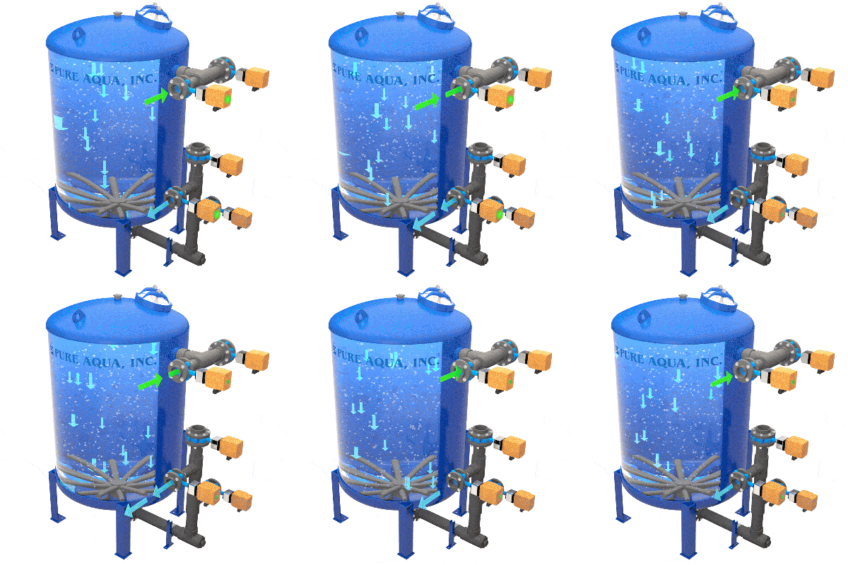
Water Media Filter System Service Flow
Why is backwashing important?
The main reason that a filter in service may need a backwash is that contaminant material may build up so much that either the water flow is hindered or the filtered water quality is no longer acceptable. This condition may be monitored with a differential pressure gauge or switch to indicate that the filter needs backwashing. A backwash should be performed when the differential pressure is greater than 10-15 psi.
Some operators may choose to initiate a regeneration cycle based on a time table or volume intervals.
During the backwash phase, water flows in the opposite direction of the normal service down flow. The backwash flow rate must be high enough that the media becomes de-compacted and expands by 40-50%. At this time the media is considered to be fluidized and acts more like the water flow than the solid filter bed.
While the media is fluidized, contaminants are allowed to slip away and escape into the filter drain where they are discarded. After about 10-15 minutes, most of the contaminants should be washed away and the filter drain should be mostly clear.
As the multimedia filter removes turbidity from the incoming feed water, eventually the filter will display a high pressure drop across the bed and/or increased turbidity levels coming from the Multi Media Filter. As a result, the multimedia filter will eventually require a backwash to clean the bed. The recommended backwash flow rate is 12-15 gallons per minute per square foot, which enough to lift the media bed sufficiently without forcing any media out of the top of the filter. Most filters are equipped with a flow restrictor on the backwash outlet that maintains this flow rate. This is important with seasonal fluctuations in water temperature, as colder water is more viscous and lifts the bed higher with less flow, which can result in losing media out of the top during backwash.
The backwash should be performed when the pressure differential (delta-P) reaches 10 psi (above clean) across the bed or when the effluent turbidity increases by 10%. A normal pressure drop across a 'clean' Multi Media Filter ranges from 3-7 psi, so this needs to be taken into consideration before initiating a backwash.
The backwash can be initiated by a differential pressure switch, via timer, PLC, digital controller or manual initiation.
The sharp edges of the sand beads and other media can become rounded over time and therefore reduce their filtration ability after many years of service and should be replaced, recommended after 5-7 years for MMF.
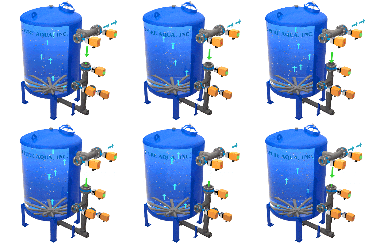
Water Media Filter System Backwash Flow
Settling Cycle
During the settle phase, the filter closes and no water flows in or out. The fluidized media is allowed to settle to form the graded filter bed. This phase may take between 15-20 minutes. This phase is not always necessary and is often skipped to save time. Also, some control systems/valves may not have this feature so that they can be offered at a lower cost.
However, it does save water and may increase the filtration efficiency. The settle phase should be seriously considered by those in places where access to water is scarce.
Rinse Cycle
After the settle phase, the rinse phase may begin. During the rinse phase, water flows in the normal service direction but is directed to drain. This gives the media time to compact itself to give more efficient filtration performance before the filter goes into service.
Some small particulate may still be present in the drained water at this time. After about 3-4 minutes, the drained water should be noticeably cleaner than the influent water. The filter bed is considered to be compacted and ready for service at that point.
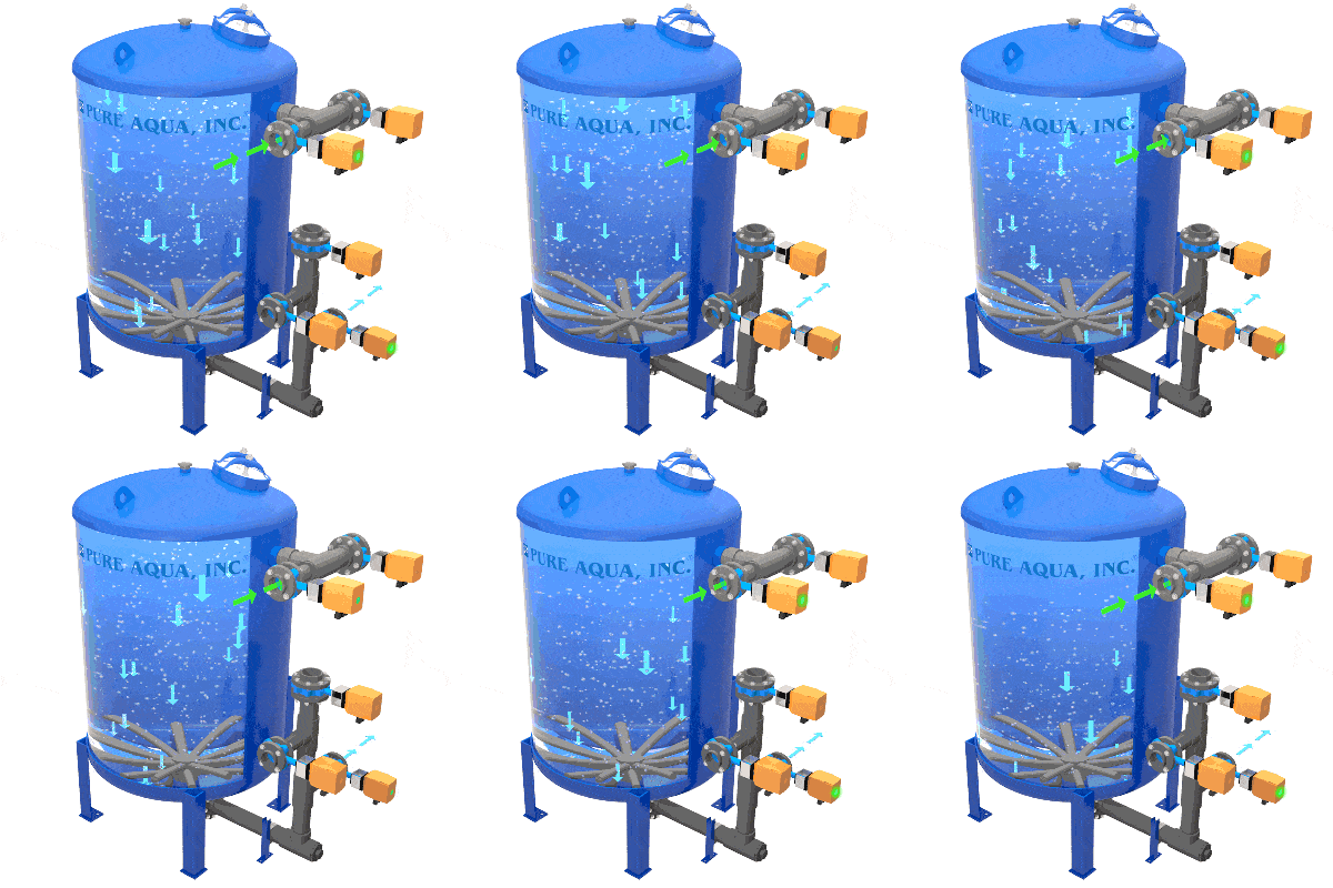
Water Media Filter System Rinse Flow
Media Filter Valves Arrangements
The figure and table below details each valve and its function. The valve position for each cycle step is noted in Table 4–1. The filters are shown with the three different valve types commonly found in our industrial media filters.
| VALVE FUNCTIONS | |||||
|---|---|---|---|---|---|
| Valve | Cycle Steps | ||||
| Service | Backwash | Settle | Rinse | ||
| A | Service Inlet | Open | Closed | Closed | Open |
| B | Service Outlet | Open | Closed | Closed | Closed |
| C | Backwash Intlet | Closed | Open | Closed | Closed |
| D | Backwash Outlet | Open | Open | Closed | Closed |
| E | Rinse Outlet | Closed | Closed | Closed | Open |
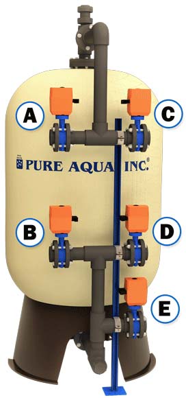
(Automatic) Actuated Butterfly Valves
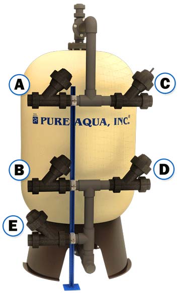
(Automatic) Diaphragm Valves
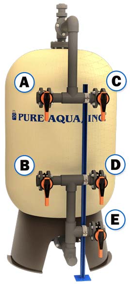
Manual Butterfly Valves
A Pure Aqua trained service technician should perform the emptying of the old media and re-loading of the new media, dosing a proper coagulant to improve filter performance and other necessary maintenance and troubleshooting.
Industries and Applications
Application for Water Media Back-washable Filters:
- Suspended solids and turbidity reduction
- Iron and manganese removal
- Groundwater remediation
- Pre-treatment for RO/NF and membrane system
- Pre-treatment for UV sterilizers
- Filtration of grey, river or surface water
- Tertiary treatment for waste water
- Cooling tower and heat exchanger
- Water features (fountains, etc.)
- Industrial process water
- Storm water
- Irrigation water
- Swimming pool water
- Potable (drinking) water
- Hotels and resorts
- Beverage and food processing
- Pretreatment media filter for reverse osmosis (RO):

Pretreatment Water Media Filter for RO - Schematic Diagram
- Pretreatment media filter for ultraviolet (UV):

Pretreatment Water Media Filter for UV - Schematic Diagram
- Pretreatment media filter for electrodeionization (EDI):

Pretreatment Water Media Filter for EDI - Schematic Diagram
- Pretreatment media filter for ion exchange:

Pretreatment Water Media Filter for Ion Exchange - Schematic Diagram
| 1 | Raw Feed Water | 8 | Reverse Osmosis System |
| 2 | Chemical Dosing: Pre-chlorination | 9 | Ultra Violet Sterilizer |
| 3 | Raw Feed Water Tank | 10 | Product Water Tank |
| 4 | Feed Pump | 11 | Product Water Pump |
| 5 | Multimedia Filter | 12 | Electro-Deionization |
| 6 | Carbon Filter | 13 | Point of Use |
| 7 | Ion Exchange Filter |
Recommended Systems and Components:
To be able to choose or recommend a multimedia filter, few information must be provided:
What type of water are you treating? Sea, city, well, surface, reclaimed? It is important to know the source of the water. Filtration velocity cross the surface area is important when we choose a multimedia filter,
- Surface water: 3-5 gallons per minute per square foot.
- Beach-Well: 5 gallons per minute per square foot, visit our MF-600 media filters
- Well Water: 5-10 gallons per minute per square foot.
- Pool Water: 15-20 gallons per minute per square foot.
What parameters are you trying to achieve? SDI less than 3? Less than 10 micron? Iron reduction? If you are selecting a multimedia filter for RO pretreatment, we should go on low velocity compared to wash water or pool water.
Will the filter be installed indoor or outdoor? This is important, for outdoor application, we should use steel or stainless steel tank, similar to our MF-1000 Series
What is the feed water temperature? For higher temperature, we recommend filters with stainless steel tank and face piping, similar to our MF-1100 Series
Are you looking for a continuous or intermittent operation? This will decide if a filtered water tank is required or not,, and will also decide on how and when to perform the filter backwash
Water Multimedia Filter Systems Projects:
Here are some completed projects:
/media-filters-projects/
Source: https://pureaqua.com/water-multimedia-filter/
0 Response to "Blue White Filter Media Direction to Install Tack Filter Media"
Post a Comment